Data Center Topologies
Data Center Topologies
Table of contents
The network topologies can be classified into tree and non-tree based topologies. This is very common observation in topology. There is another way to connect nodes are direct and indirect.
Indirect Topologies
Tree
The tree topologies are simple and broadly used in data center networks. Tree topologies may have either two or three levels. In a two-level tree, switches at the core level connect the switches at the lower level, which are referred to as edges. Servers are located at the leaves and are connected to the switches at the edge level. In a three-level tree, an intermediate level called aggregation is added between the core and edge levels.
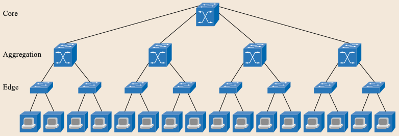
Tree is simple , but has multiple drawbacks, performance and reliability of switches should increase as we go higher in the topology levels, which would require different switches for different levels and, in turn, a move away from using commodity switches for such systems.
Fat Tree
The fat tree is an extension to tree topologies. This is widely used in commercial data center networks. Fat trees were originally proposed by Leiserson in 1985. While there have been several attempts to formalize and use fat trees since then, we found the method used by Al-Fares et al. to be the most intuitive and comprehensive.
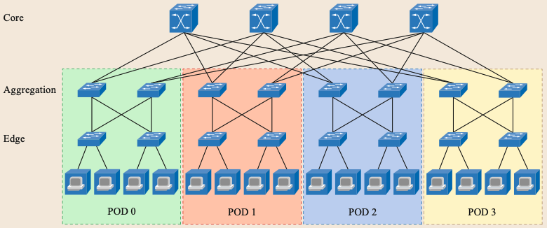
Similar to three-level tree topologies, fat trees also consist of three levels: core, aggregation, and edges. *Al-*Fares et al. adds the POD to the terminology, which consists of aggregation switches, edge switches, and servers. A k-ary fat tree contains (k/2)^2 k-port core switches and k PODs. Each core switch is connected to the aggregation layer of each POD through one port (the i-th port of any core switch is connected to POD i). Each POD has two layers of k=2 k-port switches. Switches in the upper layer (i.e., aggregation layer) are connected to core switches using k=2 of their ports. The remaining k=2 ports are used to connect to k=2 switches at the lower layer (i.e., edge layer). Each k-port switch at the edge layer uses k=2 of its ports to connect to the aggregation layer and the remaining ports to directly connect to k=2 hosts. Therefore, a k-ary fat-tree provides support for a total of k^3/4 hosts using k port switches.
Unlike tree topologies, fat trees can use commodity off-the-shelf switches at all levels. Thus, fat trees offer more flexibility and can be more cost effective compared to tree topologies.
Direct Topologies
All-to-All
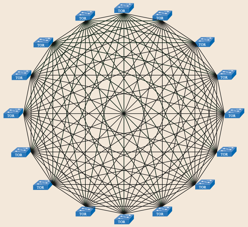
The all-to-all topology is a fully mesh topology where all the TOR connected to each other. This is a simple topology, but has few limitations, like scalability of TOR switch ports. The network growth will be limited by number of ports on the TOR switch. Another limitation is cabling, high number of cabling required.
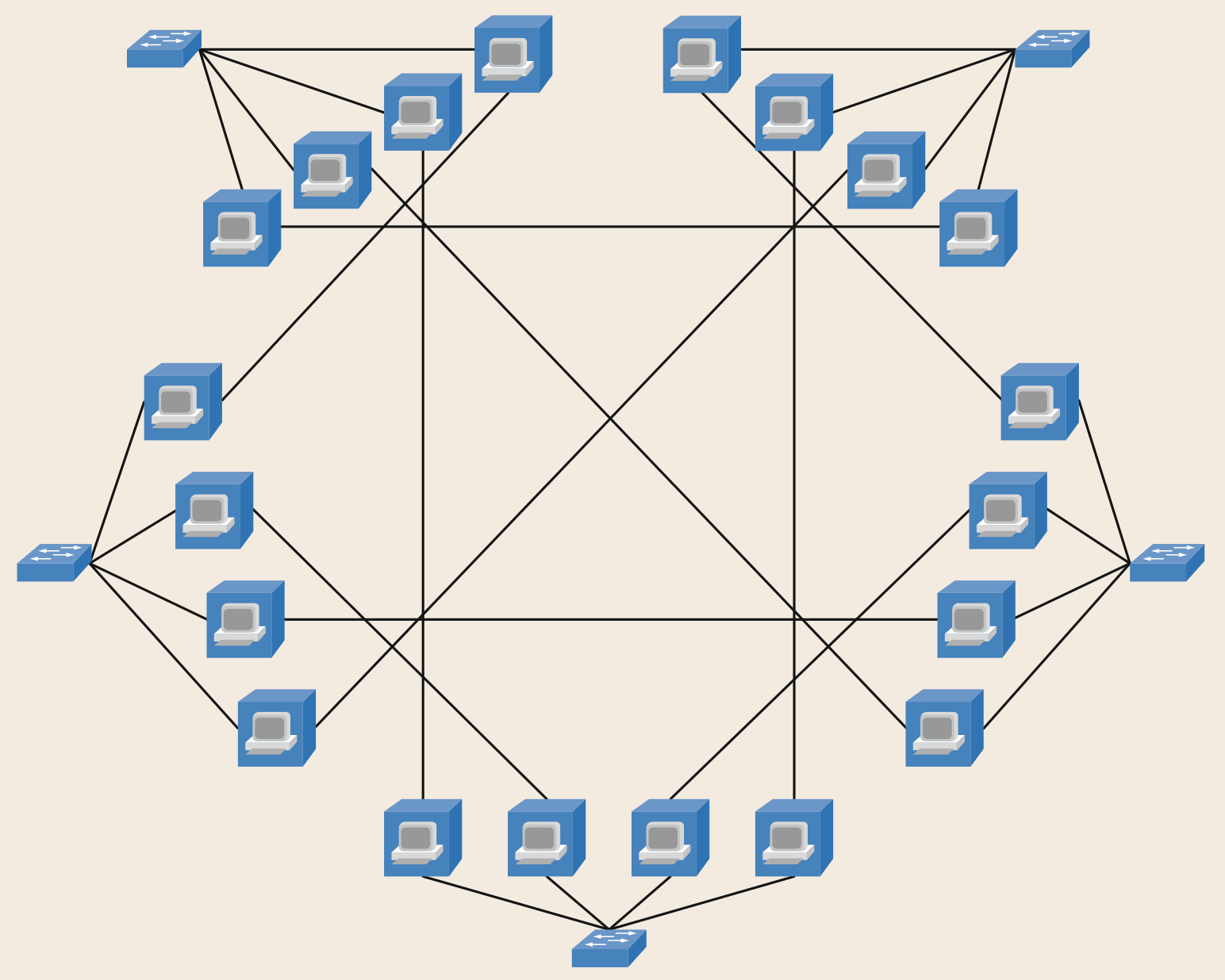
HyperX
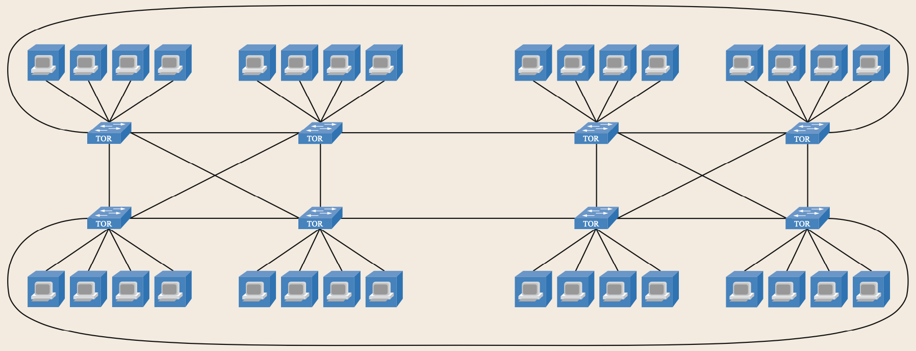
The HyperX topology, introduced for the first time by Ahn et al., can be derived from the all-to-all topology by dividing the nodes into groups (or dimensions) and by removing some intergroup links. Within a group, all nodes are fully connected. Between the groups, each node connects to all the nodes in the other groups with the same positions or coordinates. This architecture allows us to increase the scalability of the system at the expense of a larger diameter and a higher average hop count compared to the all-to-all.
In the example below, the ToR switch has four ports for inter-rack communication. This would allow us to interconnect only five racks in a full-mesh topology. By using HyperX, up to eight or nine racks can be interconnected at the expense of increasing the network diameter.
J.H. Ahn, N. Binkert, A. Davis, M. McLaren, R.S. Schreiber: HyperX: Topology, routing, and packaging of efficient large-scale networks. In: Proc. Conf. High Perform. Comput. Netw. Storage Anal., Portland (2009)
Flattened Butterfly Topology
Another popular topology is the flattened butterfly (FB) topology [23.42, 43], typically represented in rows and columns, as shown in Fig. 23.8. Each node (or ToR) is fully connected with all the nodes in the same row and column. In practice, we can consider the rows and columns as two different dimensions of a HyperX.
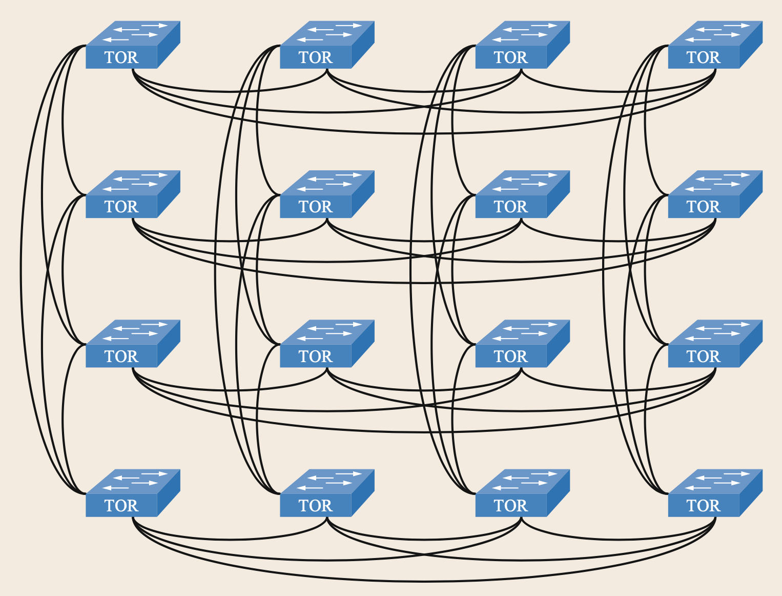
J. Kim, W.J. Dally, D. Abts: Flattened butterfly: a cost-efficient topology for high-radix networks, SIGARCH Comput. Archit. News 35, 126–137 (2007) Local Copy
W. Dally, B. Towles: Principles and Practices of In- terconnection Networks (Morgan Kaufmann, New York 2003)
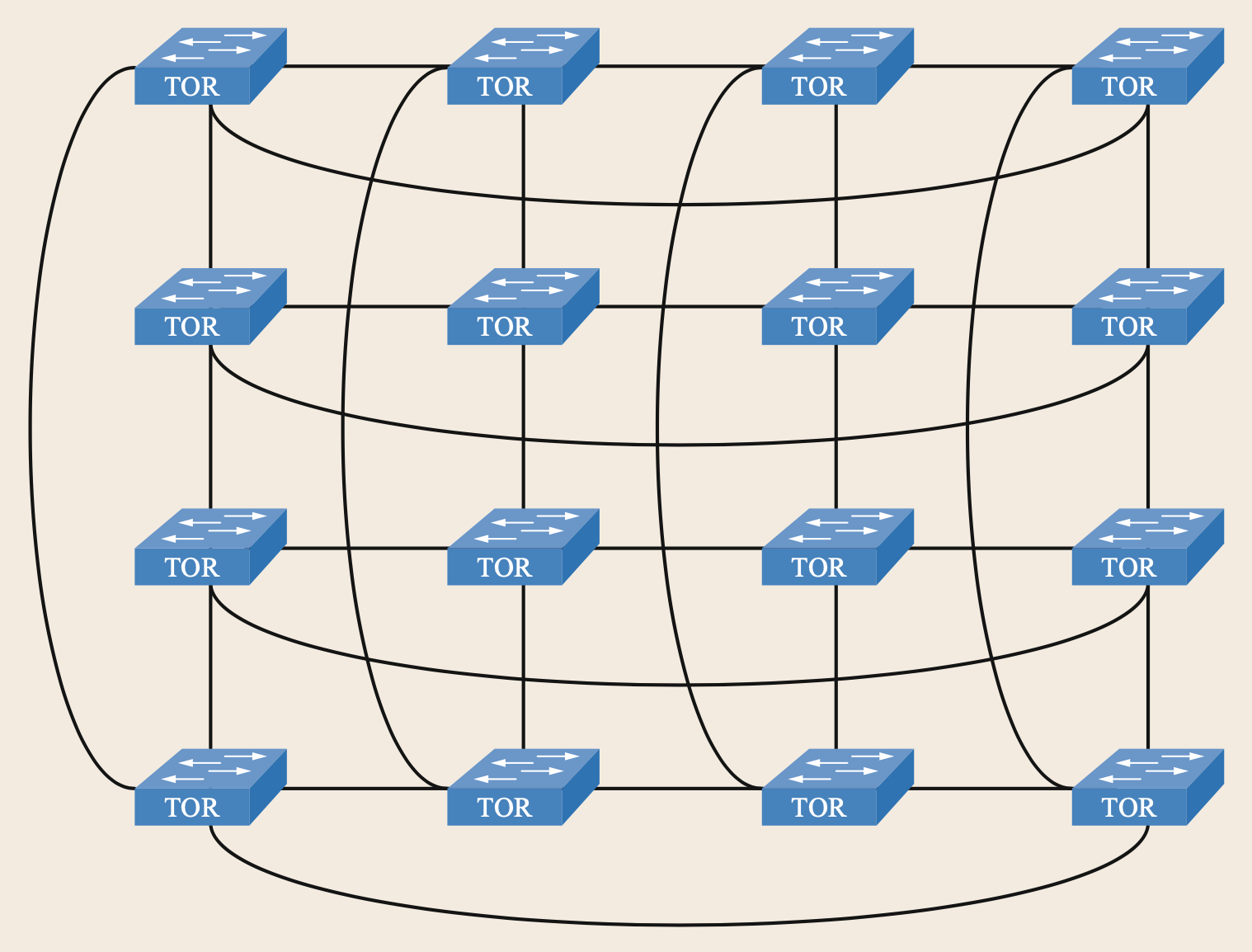
Torus
The torus topology can also be derived from the HyperX topology when assuming that each dimension is not fully connected but simply interconnected based on a ring topology.
W. Dally, B. Towles: Principles and Practices of In- terconnection Networks (Morgan Kaufmann, New York 2003)
W.J. Dally: Performance analysis of k-ary n-cube interconnection networks, IEEE Trans. Comput. 39, 775–785 (1990)
DCell & DCube
There are another two topology for data center networks.
DCell: C. Guo, H. Wu, K. Tan, L. Shi, Y. Zhang, S. Lu: DCell: a scalable and fault-tolerant network structure for data centers, ACM SIGCOMM Comput. Commun. 38(4), 75–86 (2008) Local Copy
DCube: G. Wang, D.G. Andersen, M. Kaminsky, M. Kozuch, T. Ng, K. Papagiannaki, M. Glick, L. Mummert: Your data center is a router: The case for reconfigurable optical circuit switched paths, ACM SIGCOMM Com- put. Commun. Rev. SIGCOMM 40(4), 327–338 (2010) Local Copy
LEAVE A REPLY